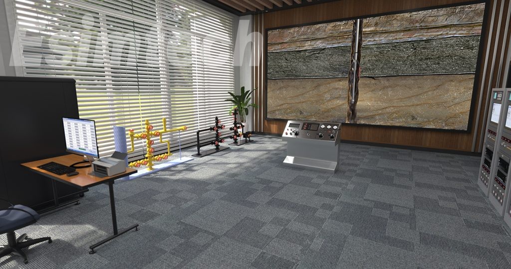
If the prospects for an oil well are not very good, logging is a very efficient method that oil and gas companies can use to collect detailed information about the various rock layers they drill through. This information can help determine more accurately whether or not hydrocarbons are present. Take out the drill pipe as well as the drill bit that is in the well. The location was outfitted with professional logging personnel and equipment, which was then used to construct a detector made up of multiple distinct logging tools that were linked together in a specific configuration determined by the number of tools contained in the component.

Utilizing a variety of scientific approaches, the length of the probe can range anywhere from 70 to 120 feet.
The probe is then lowered onto a wire rope and lowered into the wellbore. The logging personnel and geologists carefully monitored this process until the top of the probe was below the target depth. Each tool measures different types of rock and fluid properties in the geological formations that surround the wellbore. The various logging tools are activated by computers on the ground when the probe is lifted back into the borehole. This produces a graph that is known as a logging map, which represents the geological characteristics of the layers below the surface on the logging map. Tools that use gamma rays can measure any radiation that is emitted by rocks. Rocks that emit less radiation are referred to as clean rocks, and examples of clean rocks include sandstone and limestone. Clean rocks are more likely to contain hydrocarbons than dirty rocks.
It is important to take note that the line is relatively flat near the top of the well logging, and the reading continues to remain high. This suggests that the dirty rock may be shale. However, the reading changes near the bottom because the logging tool enters a sandy area that has low radiation and possibly contains oil or natural gas. This causes the reading to be unstable. Apparent resistivity curves are the name given to these sets of data, which represent the probability of the presence of water in the rock layers that surround the top wellbore of the well logging. The line is slanted to the left, which indicates that as we move further down the well logging, the formation is likely to be moist or shaly, with significant variations in measured values, which indicates that the mixture of shale or other water changes rapidly. The left formation is connected to sand that may contain hydrocarbons as the curve continues to move to the right. The following reading is known as the spontaneous potential curve, and it demonstrates to geologists how the instrument moves from one rock layer to the next. The spontaneous potential instrument makes use of two sensors, one on the surface and the other underground, to make a comparison of the natural charges that are found on the surface.
Some rock layers have positive charges, while others have negative charges when compared to the surface.
When the log is moved to the right, it indicates that positive charges are typically associated with shale, whereas when ESIM-FWL3 open hole well logging simulator is moved to the left, it indicates that negative differences are typically associated with sandstone. The readings from the resistivity tool are displayed in the middle section of the logging map. There are six resistivity curves that overlap with one another, and each one measures the conductivity of the rock at a different distance from the wellbore. The low resistance is indicated on the left side of the grid, whereas the high resistance is indicated on the right side. Rocks that contain oil or gas have a lower conductivity, and as a result, they have a greater resistance to the flow of current through them. Please take note that the electrical resistance of the rock is relatively low within the majority of the vertical distances, which may indicate that it is shale. a reading from the neutron porosity tool that can calculate how many hydrogen atoms are present in the surrounding rock - as can be seen in this section of the log - the higher the concentration of hydrogen, the higher the electrical resistance may be an indicator of sand, which is a layer that can accommodate hydrocarbons.
a reading from the neutron porosity tool that can calculate how many hydrogen atoms are present in the surrounding rockIt is possible that there is oil when the curve moves to the right; this indicates that there are hydrogen atoms. As we move down the wellbore, we can see that the amount of hydrogen typically decreases; this indicates that there are either extremely dense rocks that are unable to accommodate oil or that there may be natural gas working in conjunction with neutron porosity tools.
The density porosity tool is used to measure the size of bulk density density, which is another name for the space between electrons in rocks.
However, the log reveals that the density of the rock is decreasing as we move down the wellbore, as you will notice in the following section, the rock is becoming less dense. It is essential to ensure that the density porosity curve and the neutron porosity curve intersect at this point. The neutron curve indicates that either the rock is dense or the gas density porosity line tells us that the rock has more pores, which indicates that it cannot be a dense rock. This region shows a relatively high potential for the presence of natural gas. According to the following curve, the amount of time necessary for sound waves to be emitted into the formation and recorded back to the dense rock will have a quicker travel time, while the amount of time required by porous rocks will be longer. Finally, we can see the readings of the caliper tool that was used to measure the changes in wellbore size along the edge that is located to the left of this section.
Because the accuracy of the other tools on the probe could be impacted as a result of these changes, the computer will recalculate based on this measurement and take readings from the other tools as required. These are the most common types of logging tools that oil and gas companies use to collect information on the rock that is thousands of feet below the surface, as well as any fluid or gas that may be present. There are many other tools that are tailored to address particular logging concerns. They do not need these tools themselves to provide sufficient information to conduct an informed evaluation of oil wells; however, the combination of these tools provides a more comprehensive and reliable perspective. The more complex the geology, the more diverse the logging tools. Because the majority of oil wells are sealed off, trained geologists are able to obtain sufficient information from such logging records to create an accurate mental image of the subterranean environment. Oil and gas companies are able to use such logging records to evaluate potential drilling locations. When a company wants to drill in a new area, they can view log maps of control wells that are located nearby, arrange the log maps, and adjust them based on the surface elevation changes that occur with each well.


